SELF |
84 |
S.B. Karavashkin and O.N. Karavashkina |
|
|
|
SELF |
84 |
S.B. Karavashkin and O.N. Karavashkina |
|
|
|
We present in Table 4 the results of measurement of the
phase difference |
Table 4
|
||||||||||||||||||||||||||||||||||||||||||||||||||||||||||||||||||||||||||||||||||||||||||||||||||||||||||||||||||||||||||||||||||||||||||||||||||||||||||||||||||||||||||||||||||||
| The diagram
|
|
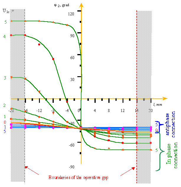
Fig. 20. The phase of emf
|
To estimate the yielded results correctly, conveniently begin with the regularity U2 (l, U1c = 0 ) selected in Fig. 19. This regularity corresponds to induction in the probe induced by one winding a. In accordance with it, as we can see in the plot, at U1c = 0 the amplitude of induced emf slightly decreases along the gap with the probe distancing from the inducing side of winding a (from right to left) from 0,0925 V at l = 16 mm to 0,06 V at l = - 16 mm. The phase of induced emf also does not remain constant and at the given conditions, in accordance with Table 4 and Fig. 20, decreases with the probe distancing from the inducing side of winding a from - 46,08 degrees at l = 16 mm to - 34,56 degrees at l = - 16 mm . With it, we can think linear with sufficient accuracy the variation of both amplitude and phase. Accordingly to Fig. 19, with in-phase connection of the primary windings, with the growing voltage across the winding c, the amplitude of emf induced in the probe diminishes, and when the voltages across the primary windings become equal, the regularity U2 (l, U1a =U1c = 5 V ) gains the appearance similar to the result yielded in previous experiment. With the anti-phase connection, with the growing voltage across the winding c, the emf grows and at the equal voltages across the primary windings, its amplitude becomes constant across the section of gap. As we can see, the yielded experimental results correspond to the pattern of process of induction between the parallel elements of primary loop and probe and are opposite to the conventional interpretation of process on the basis of interaction of flux of induction vector with the loop. The phase characteristics shown in Fig. 20 additionally corroborate our conclusion. With connection in phase and when all voltages across the primary windings were equal, the phase of emf is inverted at the axis of gap, just as in previous experiment. But with the anti-phase connection and with equal voltages at the primary windings, the phase of emf appears constant across all section of gap. This is opposite to the expected result in the view of conventional phenomenology of induction process and is fully consistent with the pattern based on the direct interaction of parallel elements of primary and secondary loops. |
Contents: / 72 / 73 / 74 / 75 / 76 / 77 / 78 / 79 / 80 / 81 / 82 / 83 / 84 / 85 / 86 / 87 / 88 / 89 / 90 /