V.4 No 1 |
75 |
| Study of electromotive force induced by heterogeneous magnetic field | |
|
|
V.4 No 1 |
75 |
| Study of electromotive force induced by heterogeneous magnetic field | |
|
|
| 2. Substantiation of the experimental technique
To understand better the essence of studied problem, let us re-read the definition of induction in time-variable magnetic field. As is known and as we mentioned in [1], the definition of induction in time-variable magnetic field is traditionally introduced by the analogy with the induction of current in a wire which crosses the force lines of magnetic field. This last has not one but two definitions. "Summing up the results of multiple experiments, we can say that the phenomenon of electromagnetic induction means that the emf arises in a wire which crosses the force lines, or in a closed wire, when it changed its coalescence with the magnetic flux. In accordance with it, we can give two formulations of the law of electromagnetic induction: first related to the section of wire and second to the closed loop. The first of them is called Faraday formulation, or differential form of the law, as it can be applied to an however small element of the loop, and the second is Maxwell formulation, or the integral form of the law" [2, p. 416]. Despite both formulations bring us to the same mathematical expression |
|
(1) |
where Eind is the emf of induction and
To make sure, consider some rectilinear loop with a
movable boundary, as shown in Fig. 2. Let this loop first be located within some permanent
magnetic field with the inductance |
|
|
Fig. 2. The pattern to determine the emf of induction
induced in the loop with a movable side, which is located in a permanent homogeneous
magnetic field with inductance |
| Calculating after the Lorenz formula, which describes the differential form of induction law, we yield the following result for the model in Fig. 2, noting the direction of magnetic field induction: "The strength of this field (the electric field of induction - authors) will be determined from the condition that the electric and magnetic forces affecting the charges within the wire are equal: |
|
|
(2) |
| or | |
|
(3) |
| or | |
| (4) | |
[2, p. 420]. As the field strength in this case arises in the unit of length of movable wire, the full value of emf will be |
|
|
(5) |
In its turn, we can express the speed of motion of movable side of loop as the variation of loop length: |
|
|
(6) |
Substituting (6) into (5), we will yield finally |
|
|
(7) |
If we calculate the induction emf on the basis of Maxwell formulation, we will yield (7). As was expected, in case of homogeneous field both formulations lead us to the same result. Now let us consider a loop with a movable side in the inhomogeneous field. To simplify, let us think the inductance of this magnetic field varying only along the axis y - i.e., in the same direction in which the movable side of loop moves, and along the movable side the magnetic field will be thought time-constant. To visualise better, suppose also that the inductance depends on y in an exponentially decreasing way like |
|
|
(8) |
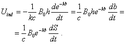
Now, calculating through Lorenz formula (3), we yield |
|
|
(9) |
Calculating after Maxwell, we have to find the integral of flux of inductance vector over the loop area. With it |
|
|
(10) |
Given (10), the expression for induction emf will be |
|
|
(11) |
Comparing (9) and (11), we see that the mathematical expressions describing the emf after Faraday and Maxwell are fully identical. And we can show that this coincidence of mathematical descriptions of phenomenon remains also in general case of movable-boundary loop interacting with inhomogeneous magnetic field. |
Contents: / 74 / 75 / 76 / 77 / 78 / 79 / 80 / 81 / 82 / 83 / 84 / 85 / 86 / 87 / 88 / 89 /