|
PAGE 4 |
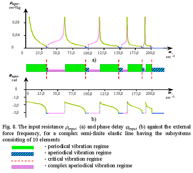
Going further approaching to the real-world models, suppose that each element of an elastic line is in its turn some elastic subsystem having some spectrum of resonance frequencies. The considered method gives here also the answers so necessary for the practice. In Fig. 8 we present the regularity of the input resistance for a semi-finite line having the resonance subsystems as a function of frequency; it is equivalent to the amplitude-frequency characteristic at the line input. We see in it a number of peaks typical for resonance systems described in literature, e.g. in [17], [23], [27] etc. None the less, there is a distinction. The scale of regimes is shown under the plot, and one can see that the aperiodical vibration regime arises first before the first resonance peak, which is absolutely untypical for usual resonance systems, not speaking that these resonance curves have been constructed for a semi-finite elastic line, where after a conventional concept of direct and indirect waves superposition the resonance conditions are absent. Furthermore, the aperiodical regime repeats before each resonance. The resonances in their turn are located at the junctions of the periodical regime and the complex aperiodical regime being new in the vibration theory. And the number of peaks is not equal to the number of subsystem elements - by rough estimation, it is twice less, which also is not typical for resonance systems. It is explained by the fact that a standard vibration process investigated above bifurcates at the critical band in the models having the subsystems, and between the critical frequency for the system as a whole (lower bound) and that for the subsystem (upper bound) the resonance phenomena seen in Fig. 8 arise. Just here may be the reason, why, with the strenght computations ideally done by conventional methods, the ruining happens sometimes in the most unexpected places. |
|
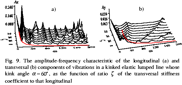
The resonance peaks appearance in elastic systems far from always is conditioned by the presence of specific bounds, heterogeneities or resonance subsystems. It is suffucient to have a kinked line with inequal longitudinal and transversal stiffness coefficients, which is typical for most of construction materials. As an example consider one such lumped system. |
|
In
Fig. 9 we show the amplitude-frequency characteristic of vibrations in a kinked elastic
line. On its start there acts an inclined harmonic force depending on the ratio |
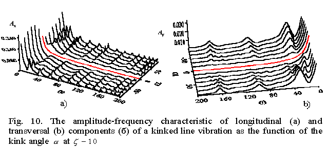 |
| In Fig. 10 we show this amplitude-frequency characteristic. One can see from it that in the kink absence (the central curve in red) the resonance peaks disappear even at inequal longitudinal and transversal stiffness coefficients.
|