SELF |
82 |
S.B. Karavashkin and O.N. Karavashkina |
|
|
|
SELF |
82 |
S.B. Karavashkin and O.N. Karavashkina |
|
|
|
| 4.2. Description of
experimental device
To realise the above experimental technique, we have modernised the previous device and inserted a framework shown in Fig. 16 onto the ferromagnetic core. |
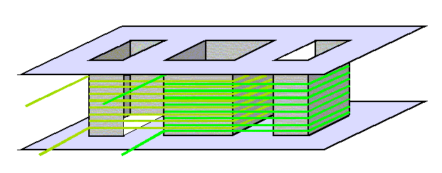 |
Fig. 16. The framework with one-layer windings set into each other |
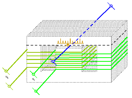
We winded onto this framework two one-layer primary windings set into each other, using the wire 0,07 mm, having the number of turns wa = wa =1200 each. So the scheme of experimental device took an appearance shown in Fig. 17. |
|
Fig. 17. Experimental device to study EM induction of the elements of primary loops parallel to the single probe
|
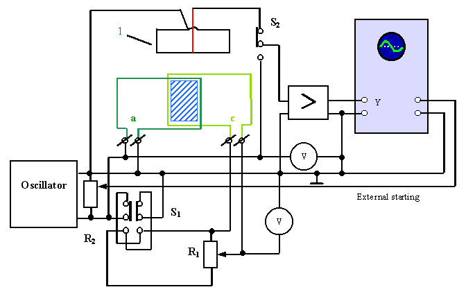
The electric circuit of this device is shown in Fig. 18. |
|
Fig. 18. Electric circuit of the device for studying EM induction of the elements of primary loops parallel to the single probe |
In distinct from electric circuit of previous study, the primary windings were fed from a power oscillator of low-frequency oscillations; in this way we were not limited by the only frequency of input current. We could change the phase of feeding of primary windings by the switch S1 . Besides, we provided the possibility to vary smoothly the amplitude of feeding voltage of the winding c at constant amplitude of feeding at the winding a, using potentiometer R1 = 120 Ohm . We also introduced some changes into the circuit of measurement. In the circuit shown in Fig. 18, the phase of inductive emf picked off the probe 1 was compared with the voltage phase at the winding a at the screen of oscillograph by way of switching the input of amplifier with the switch S2 . This allowed us to determine more accurately the phase interrelation between the voltage across the primary winding and induced emf. |
Contents: / 72 / 73 / 74 / 75 / 76 / 77 / 78 / 79 / 80 / 81 / 82 / 83 / 84 / 85 / 86 / 87 / 88 / 89 / 90 /