SELF |
28 |
S.B. Karavashkin and O.N. Karavashkina |
|
|
|
SELF |
28 |
S.B. Karavashkin and O.N. Karavashkina |
|
|
|
4. Analysis of experimental schemes for transverse dynamic fields investigation To make clear, why the diagrams shown in the previous item differ from usual experimental results in study of transverse waves, we will first of all pay our attention to the features of receivers with whose help we measure the transverse dynamic fields. When in the previous item we substantiated, how do we plot the diagrams of scalar potential of dynamic field, we emphasised that we take as zero potential the potential of space at the same point, but in absence of dynamic fields. When measuring dynamic fields, this is quite admissible but practically unrealisable condition. In reality, "usually for the purpose to determine the intensity of electromagnetic field, the field strength E of electric vector is measured, and for it on the short, medium and long wavelengths mainly rotating frame antenna is used, and on the USW - rotating horizontal either vertical antenna with symmetric feeding. Thus, the emf induced in the antenna is equal to |
|
|
(35) |
| where za is the
effective length of antenna" [12, p.
851]. Consequently, the emf is measured not in relation to zero potential, but between two
points of field, the distance between which is equal to the length of measuring antenna.
This is the first point important for understanding the features of conventional
methodology of measurement.
To reveal the second important feature of conventional
method, let us pay our attention to the typical position of measuring antenna relatively
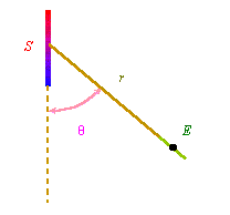
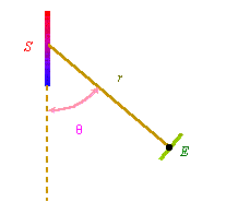
the field source. R.W. Pohl describes the process of measurement so. "We
will first study the radial component of electric field, or correspondingly the
displacement current, near the radiator. This means, we orient the radiator S
and receiver E so as it is shown in Fig. 12 a, and observe under different
radials |
|
|
|
Fig. 12 a. An example of dipole. The radial component of electric field in the near of dipole radiator [13, p. 218, Fig. 307] |
Fig. 12 b. Transverse component of dipole [13, p. 218, Fig. 308] |
Near the receiver we detect the radially
directed displacement current under any azimuth Thus, we see that conventional methods to measure the EM field strength are based on the measurement of difference of potentials with the help of measuring dipole whose length usually conforms with the studied source of field, the axis of measuring dipole is perpendicular to the radius-vector between the centres of dipoles, the measurements are carried out with the constant radius-vector by way of azimuth variation, and the measured values of field are matched up with the centre of measured dipole. From the description we clearly see that the methods used in the previous item basically differ from those which are currently used in experimental studies. |
Contents: / 12 / 13 / 14 / 15 / 16 / 17 / 18 / 19 / 20 / 21 / 22 / 23 / 24 / 25 / 26 / 27 / 28 / 29 / 30 / 31 / 32 / 33 / 34 / 35 / 36 / 37 / 38 /